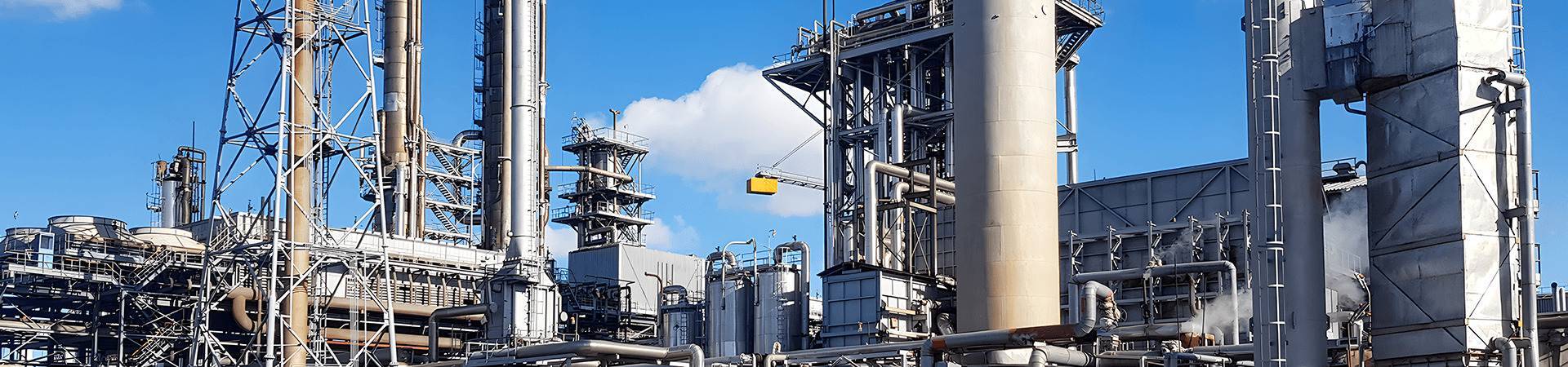
Jinzhou Petrochemical Mass‑Produces SEMI G3 & G5 Electronic Grade Isopropyl Alcohol for Semiconductor Wet Cleaning
Jinzhou Petrochemical’s light ends purification trains operate on a propylene hydration route in which refinery-grade propylene is first caustic-washed, dried over molecular sieves, and catalytically hydrated to 2-propanol. The crude 2-propanol is purified through a benzene-free azeotropic distillation sequence, followed by multi-stage cation/anion exchange and nanofiltration to reduce chloride, sulfate, sodium, aluminum, iron, copper, nickel, and zinc to grades suitable for semiconductor wet cleaning. The electronic grade output is separated from industrial grade material by dedicated transfer lines, surge tanks, and filling heads to prevent cross-contamination. Filling for SEMI G3 and SEMI G5 containers takes place in an ISO 14644-1:2015 Class 4 cleanroom with vertical unidirectional airflow, where total particle concentrations are maintained below 352 particles/m³ at ≥0.5 µm. Product is passed through 0.05 µm PTFE membrane cartridges at point of fill, and nitrogen blanketing maintains dissolved oxygen below 1 mg/L. Lot release protocols include GC-FID purity analysis per SEMI C1, Karl Fischer water titration per ASTM D1364, ion chromatography per EPA 300.1, sector-field ICP-MS per EPA 200.8, and laser particle counting calibrated with 0.1 µm polystyrene latex spheres. The two grades differ chiefly in trace metal, anion, and particle burden: SEMI G3 is suited to noncritical wafer handling and tool parts cleaning, while SEMI G5 is specified for direct contact with patterned wafers at ≤14 nm nodes. Published data for this specific production configuration is limited, but the analytical acceptance limits shown in Table 1 are aligned with semiconductor-grade 2-propanol supply specifications.
| Parameter | Reference method | SEMI G3 limit | SEMI G5 limit |
|---|---|---|---|
| Purity (GC area %) | SEMI C1 | ≥ 99.80 % | ≥ 99.99 % |
| Water (Karl Fischer) | ASTM D1364 | ≤ 0.100 wt% | ≤ 0.030 wt% |
| Residue after evaporation | ASTM D1353 | ≤ 5.0 ppm | ≤ 1.0 ppm |
| Acidity as acetic acid | ASTM D1613 | ≤ 1.0 ppm | ≤ 0.5 ppm |
| Chloride | EPA 300.1 | ≤ 0.20 ppm | ≤ 0.05 ppm |
| Sulfate | EPA 300.1 | ≤ 0.30 ppm | ≤ 0.05 ppm |
| Sodium | EPA 200.8 | ≤ 5.0 ppb | ≤ 0.10 ppb |
| Aluminum | EPA 200.8 | ≤ 5.0 ppb | ≤ 0.10 ppb |
| Iron | EPA 200.8 | ≤ 10.0 ppb | ≤ 0.10 ppb |
| Copper | EPA 200.8 | ≤ 5.0 ppb | ≤ 0.10 ppb |
| Nickel | EPA 200.8 | ≤ 5.0 ppb | ≤ 0.10 ppb |
| Particles ≥0.04 µm | SEMI C1 LPC | ≤ 200 counts/mL | ≤ 25 counts/mL |
| Particles ≥0.20 µm | SEMI C1 LPC | ≤ 50 counts/mL | ≤ 10 counts/mL |
| APHA color | ASTM D1209 | ≤ 10 | ≤ 5 |
How Does Residual IPA Redistribute Trace Metals on Hydrophilic Wafer Surfaces?
In front-end-of-line pre-diffusion cleaning, the final IPA rinse or vapour dry step follows RCA SC-1 (NH4OH:H2O2:H2O at 1:1:5) and SC-2 (HCl:H2O2:H2O at 1:1:6) sequences used to remove particles, organic residues, and metallic contaminants. After deionized water overflow rinsing, residual water on the oxide surface is displaced by IPA because the surface tension of pure 2-propanol is 21.7 mN/m at 25 °C, compared with 72.0 mN/m for water. The fluid replacement reduces capillary stress during drying and prevents water-spot formation, but it also introduces an evaporation front in which any dissolved nonvolatile impurity concentrates at the wafer–liquid–air meniscus. Trace sodium and potassium at ≥1 ppb in the IPA layer can deposit on the exposed gate oxide and shift flatband voltage in capacitor test structures; aluminum, iron, and copper above 5 ppb are measurable by TXRF after 120 s of immersion. Production-scale single-wafer spin cleaning tools therefore use SEMI G5 IPA for final rinsing at dispense rates of 120 mL/min to 240 mL/min onto 300 mm wafers rotating at 800 rpm to 1,500 rpm, with point-of-use filtration at 0.03 µm to 0.05 µm to remove particle shedding from pump diaphragms and tubing. Water content above 0.10 wt% in SEMI G3 material is acceptable only for non-device-contact rinsing because higher water fraction collapses the surface tension gradient and increases the critical particle adhesion diameter. In immersion baths, the bulk solvent is recirculated at 20 L/min through ion exchange cartridges and hydrophobic PTFE membranes to maintain cation concentrations below 0.1 ppb; batch-to-batch variance in acid-titratable acidity above 0.5 µeq/kg has been shown to increase oxide surface roughness from 0.12 nm to 0.18 nm RMS by AFM on 1 µm × 1 µm scans. The operational boundary for direct wafer contact is therefore defined by the combination of water, trace metal, and nonvolatile residue; the solvent must not be returned to the bath after contact with ambient air for more than 24 h without revalidation of moisture and particle counts.
An additional limiting factor is the interaction between residual IPA and subsequent high-k or metal gate deposition. In batch cleaning, a 2-propanol film of 10–20 nm thickness may remain after spin-off if the wafer edge exclusion is set below 2 mm; this film can react with ozone ash or plasma to generate acetone and organic acids. The acetone fraction measured by MIR-ATR on control wafers remains below 0.01 monolayers after a 60 s nitrogen purge at 25 °C, but the purge efficiency drops when relative humidity exceeds 55 %. For that reason, dryers maintain relative humidity at 40–50 % and purge gas temperature at 40 °C; the chamber is sealed against room air infiltration to keep chamber oxygen below 2.0 vol%, well below the lower flammable limit of IPA in air at 2.0 vol% to 12.7 vol%. This is critical because a 300 mm batch of 25 wafers can carry 0.5–1.0 L of IPA vapour into the exhaust duct during a single dry cycle, and the exhaust abatement must handle a flash point of 11.7 °C and an autoignition temperature of 399 °C.
Back-end-of-line residue removal on fluoropolymer-passivated aluminum bond pads and porous low-k dielectrics places strict limits on solvent impurity profiles because chloride and sulfate residues can initiate under-etch or corrosion during subsequent barrier CMP. In these cleaning steps, electronic grade IPA is blended with cyclohexanone or propylene glycol monomethyl ether acetate at volume ratios from 1:5 to 1:20 depending on post-etch polymer loading. The blends are dispensed through 0.05 µm PTFE point-of-use filters into immersion or single-wafer spray tools at temperatures between 40 °C and 70 °C. Because UV-cured porous low-k dielectrics can exhibit methyl silsesquioxane crosslinking at thermal budgets as low as 250 °C, residual sulfur-bearing species above 0.1 ppm in the solvent can form sulfonic acid derivatives during subsequent anneal, as detected by FTIR absorbance near 1,170 cm⁻¹. The ion chromatography limit of 0.05 ppm for sulfate in SEMI G5 IPA is therefore applied to blends irrespective of dilution factor. A similar constraint applies to chloride, which accelerates corrosion of exposed titanium-tungsten liners and aluminum-copper pads when the total acid concentration in the solvent exceeds 0.05 µeq/g. Production-scale solvent recovery loops on 300 mm single-wafer tools run with 15–25 L reservoir sizes and continuous distillation; published data for this specific configuration is limited, but tool-level resistivity and pH monitors are set to alarm at 18 MΩ·cm and 6.5–7.5, respectively, to prevent back-contamination from degraded photoresist stripping by-products. Field observations from manufacturing lines indicate that switching from SEMI G3 to SEMI G5 IPA in a 10:1 PGMEA blend reduces post-clean defect density by roughly one-half to one-third when the primary defect is metal-containing residues, although the exact improvement depends on ash chemistry and dielectric porosity. The solvent compatibility envelope excludes chlorinated solvents and strong oxidizing acids in the same bath; inadvertent mixing with sulfuric acid/hydrogen peroxide residues from prior upstream steps can raise bath temperature above 60 °C and produce acetone through oxidative dehydrogenation, shifting the GC purity of the recovered IPA below 99.5 % and creating a flammability hazard in the exhaust system.
For sub-7 nm logic, the use of low-metals IPA extends to wetting of contact clean after reactive ion etch. The single-wafer dispense nozzle is purged with nitrogen between dispenses to prevent crystallized residue at the tip; tip purge flows of 2 L/min are maintained while the wafer rotates at 500 rpm to 1,800 rpm. The liquid velocity at the wafer edge generates shear stress above 50 Pa, which assists removal of polymeric residues but also generates submicrometer aerosol; exhaust plenums are designed to capture droplets larger than 0.1 µm before they can redeposit. In these tools, the total organic carbon content of the IPA feed is kept below 500 ppb, and the final rinse is dispensed for 20 s to 40 s to displace dissolved resist by-products. The lack of uniform published data for residue removal efficiency on specific post-etch structures does not reduce the requirement to validate each lot by ICP-MS; acceptance criteria are typically set at ≤0.1 ppb for alkali and transition metals and ≤0.03 wt% water for direct contact after silicide contact formation.
When Vapour-Dryer Meniscus Gradients Are Modulated by IPA Concentration
In a nitrogen-inerted vapour dryer, a 300 mm wafer cassette is withdrawn from ultrapure water through a zone where nitrogen carries vaporized IPA. The surface tension difference between water-rich and IPA-rich regions at the three-phase meniscus induces Marangoni flow that sweeps liquid water back into the bath, leaving a film-free wafer surface. The driving force depends on the IPA concentration in the gas phase; at 2–5 vol% IPA in nitrogen, the local surface tension gradient at 70 °C is approximately 0.15 mN/m per mm of meniscus length, sufficient to overcome receding dynamic contact angle hysteresis on hydrophilic oxide. The evaporation rate is controlled by the carrier gas temperature, typically 65–80 °C, and the liquid IPA reservoir temperature of 20–25 °C, producing a stable vapour concentration without aerosol condensation. The sensitivity of this process to trace water and nonvolatile residues is amplified because the vapour phase selectively transports volatile IPA while leaving nonvolatile impurities in the liquid reservoir; however, if the reservoir is contaminated with metal ions from reused solvent or from stainless steel tubing, sub-0.1 µm aerosol droplets may carry these impurities to the wafer edge during the final 5 mm of withdrawal. For this reason, the liquid IPA reservoir is filled from SEMI G5 drums through 0.02 µm PTFE filters and is replaced every 48 h of continuous operation; the carrier nitrogen is filtered at 0.003 µm and monitored for oxygen, which must remain below 1.0 vol% to stay below the 2.0 vol% lower flammable limit.
The chamber pressure is kept at 50–100 Pa above atmospheric to exclude particulate ingress, and the withdrawal velocity is ramped from 0.5 mm/s at the wafer edge to 2.0 mm/s through the bulk of the wafer, then reduced to 0.3 mm/s for the final edge. This velocity profile minimizes fluid pinch-off at the edge beads, where water droplets with diameters above 0.2 µm may remain if the IPA concentration drops below 1.5 vol%. Production-scale Marangoni dryers on 300 mm wet benches show particle adders greater than 0.065 µm of fewer than 20 per wafer when the IPA reservoir is maintained below 0.1 ppb total trace metals and water below 0.03 wt%; when the water content increases to 0.10 wt%, the surface tension gradient between water and vapour-phase IPA collapses, and water-spot defects increase by more than an order of magnitude on high-aspect-ratio shallow trench isolation structures. The operational boundary for direct contact with high-aspect-ratio DRAM cells is therefore set at ≤0.03 wt% water, ≤0.1 ppb each for sodium, potassium, aluminum, iron, copper, and zinc, and ≤10 particles/mL at ≥0.04 µm. The use of residue from previous industrial-grade IPA or reclaimed solvent is incompatible with this step because even non-detectable by GC purity differences do not capture trace nonvolatile concentrations; only full lot certification by ICP-MS and LPC is accepted for the reservoir.
Reticle Bath Life Extension with SEMI G5 Isopropyl Alcohol
Reticle cleaning baths for 193 nm photomasks and deep ultraviolet layers present a particularly narrow contamination window because the mask surface is inspected at 0.05 µm sensitivity and repaired in an environment where any added organic or metallic contamination creates printable defects. The use of SEMI G5 2-propanol as the final rinse after sulfuric acid/peroxide or ammonium hydroxide/peroxide cleaning avoids sulfate, ammonium, and chloride deposition that can form ammonium sulfate haze at 193 nm wavelengths. Batch mask cleaners typically operate at 70–90 °C for acid chemistry, followed by overflow hot DI water rinse at 50 °C, then a 6–10 min IPA rinse in a sealed quartz vessel. The IPA bath is recirculated at 10–15 L/min through 0.03 µm PTFE cartridges and a cation-exchange resin bed to maintain cations below 0.05 ppb; bath life is extended from 72 h to 168 h when the initial solvent is SEMI G5 rather than SEMI G3, based on haze density measurements across 13 × 13 inspection points.
The final rinse is followed by spin drying at 1,200 rpm with nitrogen purge at 30 L/min and a chamber pressure of 10 Pa positive. Residual IPA on the mask surface measured by thermal desorption GC/MS must be below 0.5 ng/cm² before pellicle mounting; above this threshold, pellicle adhesive outgassing and organic haze formation during a 20 kJ/cm² DUV exposure test can increase. The specification overlay is governed by SEMI C18 for solvent purity, while the cleaning equipment is validated against ISO 14644-1:2015 Class 3 internal environmental conditions. Incompatibility arises with ammonia-containing cleaning chemistries when the rinse bath is allowed to accumulate ammonium hydroxide above 0.1 ppm; this elevates the pH above 8.5 and initiates ammonium sulfate haze formation on chromium oxide mask layers. The same bath cannot be used for both acid-strip and ammonia-strip reticle cleaners without an intermediate DI water purge and pH monitoring because carryover exceeds 0.05 ppm sulfate and creates a visible haze within 48 h.
Copper/low-k CMP slurries contain colloidal silica or ceria particles that adhere to dielectric and barrier surfaces through van der Waals and electrostatic forces; IPA rinse reduces surface tension and solubilizes organic contaminants from benzotriazole passivation layers. In post-CMP scrubber tools, point-of-use blending of SEMI G5 IPA with deionized water at 5–10 vol% mitigates galvanic corrosion between copper and tantalum barrier liners. The rinse pH is maintained at 6.5–7.5 by dilute ammonium hydroxide or citric acid, and the IPA stream is filtered through 0.04 µm nylon or polypropylene cartridges to avoid particle shedding. Total organic carbon levels in the rinse bath must remain below 500 ppb to prevent pad and brush degradation; scrubber brushes made of polyvinyl acetate are replaced after 500 wafer passes or when extracted debris increases the LPC background by 50 particles/mL at ≥0.2 µm. The critical processing window is narrow: if the IPA concentration drops below 3 vol%, the contact angle on copper exceeds 40°, and the scrubber brush cannot maintain uniform contact; if the concentration exceeds 15 vol%, the flash point of the rinse approaches room temperature and becomes a fire hazard in the enclosed tool.
Production-scale data from 300 mm copper CMP scrubbers show that the average post-clean defect count for ≥0.16 µm particles remains below 12 defects per wafer when the SEMI G5 IPA concentration is held at 8 vol% and the dispense flow is 1.5 L/min; elevating the trace iron concentration in the IPA to 5 ppb raises the same count to 30 defects per wafer by converting benzotriazole into insoluble iron complexes. The solvent is not reused directly after the scrubber because organic residues, copper ions, and abrasive particles accumulate; waste streams are segregated and sent to solvent recovery, where distillation raises the IPA purity above 99.8 % but does not reduce nonvolatile metals to G5 levels without additional ion exchange and nanofiltration. The compatibility of SEMI G5 IPA with typical post-CMP cleaning hardware is constrained by fluoropolymer seals and HDPE containers; polytetrafluoroethylene is preferred for long-term contact because plasticizer leaching from flexible PVC or unfluorinated polyethylene can exceed 100 µg/L after 72 h at 40 °C.
Controlling Leachable Fractions in Fluorinated HDPE Packaging
Fluorinated high-density polyethylene drums and intermediate bulk containers are widely used for electronic grade IPA because they eliminate steel corrosion and reduce metal leaching while keeping logistics costs lower than PTFE-lined stainless steel. In long-term storage, however, the fluorinated HDPE surface can release low levels of oligomers, chloride, and aluminum, and the permeation rate of oxygen through the polymer wall must be controlled to prevent formation of acetone and peroxides. Storage tests per ASTM D543 with SEMI G5 IPA at 40 °C for 72 h show extractable total organic carbon below 0.25 µg/g and total trace metals below 0.05 ng/mL for high-quality fluorinated HDPE, whereas unfluorinated HDPE can exceed 1.0 µg/g TOC and 0.5 ng/mL aluminum under identical conditions. The filling plant therefore uses only fluorinated HDPE lots that pass a 14-day solvent pre-leach with 99.99 % IPA at 40 °C, followed by extraction and ICP-MS analysis; this validation is repeated for each new resin lot to account for polymer molecular weight distribution.
| Material | Maximum service temperature | Extractables in IPA after 72 h at 40 °C | G5 compatibility |
|---|---|---|---|
| Virgin PTFE | 260 °C | <0.01 µg/g TOC | Compatible |
| PFA | 260 °C | <0.05 µg/g TOC | Compatible |
| PVDF | 150 °C | <0.10 µg/g TOC | Compatible |
| Fluorinated HDPE | 60 °C | <0.25 µg/g TOC | Limited to 30 days |
| Electropolished 316L stainless steel | 100 °C | <0.05 µg/g iron | Compatible with validation |
| Polypropylene | 80 °C | <0.40 µg/g TOC | Not recommended for G5 |
| Flexible PVC | 40 °C | >1.0 µg/g plasticizer | Incompatible |
Transfer lines at the point of use are constructed of PVDF or PFA with 6.35 mm to 12.7 mm inner diameter, and connections use perfluoroelastomer O-rings that show <0.1 µg/cm² extractable organics after 24 h in 2-propanol at 60 °C. The distribution loop is pressurized with nitrogen to 200 kPa and recirculated at 10 L/min to keep particle counts below 10/mL at ≥0.04 µm; stagnant zones longer than 5 pipe diameters are prohibited because they generate microenvironments where water and hydrogen peroxide can concentrate above the bulk specification. This packaging and distribution design is compatible only with SEMI G3 and SEMI G5 IPA that has been pre-filtered at 0.05 µm; reclaim material with higher residue should not be introduced into the same distribution loop because polymer extraction rates are accelerated by acetone, peroxides, and organic acids above 0.1 ppm.


